The Member Info Tab
The Member tab is only available when a member is selected in the Job Tree. The properties specified here affect only the member selected.
Properties include:
Save as Default
In the top right corner of the tab is the Save as Default button. This will save your Member Notes, Multiple Member Connection selection (where applicable), Deflection Criteria and Member Settings (where applicable) as default settings for future jobs.
Note: Only warn when exceeding upward deflection limits, Only warn for excessive uplift, and Apply seismic overstrengh design are Member Settings that do not Save as Default.
Quantity
For use with the Material List Report on the Job Summary tab, this user input field is used to add additional quantity of the designed member. The field must be greater than or equal to 1, the default quantity is 1, and is limited to 4 digits (max. 9999).
System and Member Type
This feature is available for joists and beams. If you want to change the existing member to a different system and/or member type, select an option from the drop-down menu and the Convert Member button will become available to change the member. Once the button is selected, the current member will update to the newly selected member. The Member Notes will update to include the member type it was converted from.
The remaining tabs will update based on the changed member type. All user defaults will remain as long as they are still valid, if not, they will reset to the system defaults. Remember to check all support and loading information before proceeding to design the member.
Member Notes
Printed only on that individual member's report. They will display on both the Report tab and the printed report.
Member Pitch
Available only on roof members (disabled for Hip/ Valley members). Allowable range is 0/12 -12/12.
Display Multiple Member Connections as
This section is only available for beam member types in residential and commercial applications and allows you to designate how Multiple Member Connections are displayed. Your choices are: None, Full Length, By Span, and Detailed-Loads Only.
-
None: A solution won't be defined for this member.
-
Full Length: Will provide the same solution across the full length of the member
-
By Span: Will provide a separate solution for each span along the member
-
Detailed-Loads Only: Provides the loading to be considered for the connection but won't provide a solution.
Multiple Member Connections can also be referred to as Multiple Ply Connections.
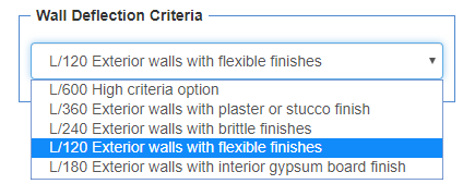
This section allows you to change the deflection criteria for the individual member. Your choices are High, Improved, Code Minimum, and Custom. Selecting Custom will allow you to enter your own Live Load and Total Load values.
For Floor and Roof Members
Deflection criteria are a set of deflection limits that apply to floor and roof members and are defined by building codes. These deflection limits are intended to ensure user comfort and to prevent excessive cracking of finish materials. The job default setting may be changed for any member using the individual Member Tab. However, the software will only accept deflection limits that are equal to or more stringent than minimum building code requirements.

For additional information on Deflection Criteria see the Deflection Criteria topic.
For Walls
Unlike for floor systems, the contribution of wall sheathing to the stiffness of the wall system is not considered in deflection calculations out of the plane of the wall. It is also important to note that Forte calculates factored wind loads that include CpCg factors for both inward and outward wind pressures. The calculated load for component and cladding load is applied laterally to the wall member for strength design and 42% of this load is used for stiffness design (IBC Table R1604.3, footnote f).Calculated deflection also includes the effects of eccentricity of axially applied loads.
In the referenced version of CSA O86, the informative Annex A (General Design) contains a section "Elastic deflection of stud wall systems under wind load", which suggests that typical stud wall systems should be designed for an out of plane deflection criteria of L/360 for brittle finishes such as brick. However, this section of the code is non-mandatory and included for information purposes. Organizations such as the Brick Industry Association suggest an L/240 criteria for brick veneer with wood stud walls. This is consistent with model codes in the United States.
Acceptable deflection limits are usually established by the design professional of record, finish material provider, and/or building code authority. Software does not allow for the requirements in IBC section 1604.3.7 regarding deflection criteria for member supporting glass.
For Wall Studs
Wall Configuration Details allow for the selection of different wall configurations based on external sheathing requirements. For additional information, see the Wall Configuration Details topic.
See the Wind Loading topic for more information. For additional information on Deflection Criteria see the Deflection Criteria topic.
- Allow TJI Web Stiffeners at End/ Intermediate Supports: Select these two options so that the system will automatically place web stiffeners over end and/or intermediate supports when higher joist bearing control values are needed.
- Allow TJI Cantilever Reinforcement: Select this option so that the system will automatically place panel reinforcement to the side(s) of the joist when additional strength and stiffness is needed at cantilever ends. Cantilever reinforcement assemblies are fully defined in the TJI Specifier's Guide (Series "E" details).
- Allow Repetitive Member Increase: Determine if all repetitive joist members in the job meet the requirements defined by code to allow for this increase to moment capacity. This increase applies to rectangular joist products only and will only show as an option for a Floor Joist member type. It does not apply to TJI joists. See the Repetitive Member Increase topic for more information.
- Allow removal of supports with excessive uplift: The temporary removal of a support during a specific load combination and load pattern analysis.
- Only warn when exceeding upward deflection limits: Check this box when you want a warning, not a design failure, for exceeding the limits of upward deflection (only for Floor Beams and Floor Joists, and anywhere support removal is available). This member setting will not save as default, meaning you will have to check the box each time you want this applied to a member within a job.
- Only warn for excessive uplift: Select this option when you want a warning, not a design failure, for excessive uplift (only for Floor Beams and Floor Joists, and anywhere support removal is available). This member setting will not save as default, meaning you will have to check the box each time you want this applied to a member within a job.
- Apply seismic overstrength design: Check this box if you want to apply overstrength from the seismic loading tab (found at the job level). Only available for beams and IBC 2018 and newer.
Minimum Load Bearing Length
This section is only available for members in jobs creating NBCC designs and allows you to set a Load Bearing Length for point loads. Although point loads are idealized as points with no length within the analysis model, they have some physical length to them. The length of point loads is known as the load bearing length.
The load bearing length is used when determining controlling conditions for support reactions and the required bearing length in the member report. The load bearing length and support length are used to calculate an average bearing length. The average bearing length is used to calculate the support bearing capacity and required support length.
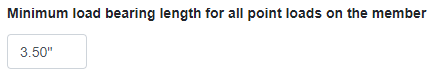
Input the length (in inches) for the point load bearing length. This length is used for all point loads. The minimum length is 3.5 inches and the maximum length is 14 inches.
You can return to your original settings by going to User>Settings and clicking on the Reset All Job Defaults button. This will reset all your saved defaults for each Member Type as well as your Job and Level Settings. This command will NOT affect any settings shown in the Settings dialog.