The Spans and Supports Tab (Horizontal Members)
Use the Spans and Supports tab to enter:
- Dimensional information for spans as they appear on architectural plans
- Dimensional and material information about the supports
- The major specifications for the member being sized
- Unbraced length considerations for the Top and Bottom edges
You can enter unlimited spans for each member. To view the member graphic, select the 
As you make changes in the grid, you will notice the graphic does not update immediately. This is intentional and was done to allow you to navigate through the fields in the grid faster. Once you have stopped making changes for a few seconds, the graphic will update. You do NOT need to wait for the graphic to update before switching to another tab.
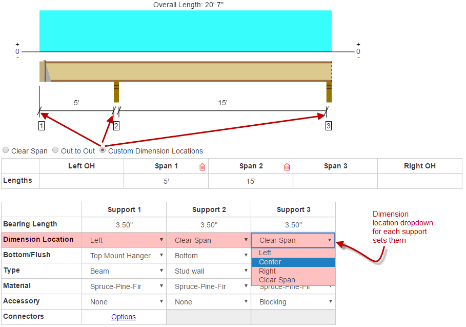
Dimension Location Options
ForteWEB software allows you to customize how dimensions are displayed for each member in the job tree. Customizing these dimension locations allows you to easily match dimensions from architectural plans, without having to add or subtract support widths.
- Out-to-Out: Sets dimension locations at the outside face of end supports. Intermediate supports have dimension locations at the middle of the support.
- Clear Span: Sets dimension locations at the inside faces of end supports and intermediate supports.
- Custom Dimension Locations: This setting activates the Dimension Location row in the Supports grid, allowing you to customize dimensions by support.
Changing the Dimension Location option changes the overall length of the member.

Span Length
Enter the length of each span in the text boxes. Note that each time you enter a new span length and press the Enter or Tab key, the system generates a new span text box.
Left OH/Right OH
Enter the length of the left and right overhangs if they exist. Design of steel members do not currently analyze cantilevers, and as such an error message will appear on the report.
Span Length text boxes
Enter the distance between the first two supports that run along the project member in the Span 1 text box. Continue entering span information for all remaining spans.
Cantilever Lengths


Support information
Use the Tab key to navigate the fields in the Supports grid. Use the up/down arrow keys to select values from the drop-down menus. Using Alt+ up/down will display the list of available selections.
Bearing Length
Enter a length for each support.
Dimension Location
- Left
- Center
- Right
- Clear Span
Bottom/Flush
- Bottom: Available for all structural systems; a member's bottom edge sits on top of a structural bearing directly below
- Top Mount Hanger: Available for floor and roof systems
- Face Mount Hanger: Available for floor and roof systems
Type
The availability of support types depends on a support being bottom or flush and on the member type. For example, the column and trimmer support type options are not available for joists. Also, plate on steel support type is not available with face mount hangers because such a hanger cannot be nailed or welded to a steel top plate.

Material
The availability of support materials depends on whether a support is bottom or flush, and on the support type. For example, a stud wall as a bottom support offers only TimberStrand® LSL as an option because you can use this material as a wall plate, but a flush support using a beam support type offers the entire Weyerhaeuser® SCL product line as support material. Depending on member selections, the options are:
- TimberStrand® LSL
- StrandGuard® LSL
- Parallam® PSL
- Microllam® LVL
- Glulam
- Hem Fir
- Southern Pine
- Doug Fir
- Spruce Pine Fir
A list of bearing values for support materials can be found in the Support Material Bearing Values.
Accessory
Flush supports have no accessory options. The following options available for bottom supports:
- Blocking
- 1" Rim Board
- 1 1/8" Rim Board
- 1 1/4" Rim Board
- 1 1/2" Rim Board
- 1 3/4" Rim Board
- None
Options: This option is available when you select a Top Mount or Face Mount Hanger.
Bracing Grid
This grid allows you to specify unbraced length spacing for the Top and Bottom edges of your member.
Choosing Maximum Allowable will analyze the member and return the Maximum Unbraced Length for the Top and Bottom Edges on the Member Report. Unlike the other options, Maximum Allowable must be selected for both edges in order to be analyzed.
If you choose one of the other options- Full Length, All Supports, End Supports Only, or Custom - you can use any combination to specify different bracing criteria for the Top and Bottom Edge.
Types of bracing for horizontal members:
-
Full Length bracing is considered as continuous or repetitive member bracing placed at short intervals. Examples include attached sheathing (top edge), drywall or gypsum (bottom edge), and perpendicular strapping (bottom edge).
-
All Supports indicates lateral bracing is placed perpendicularly on each side of the member over each support location. Examples include blocking or rim board (only at end locations).
-
End Supports Only indicates lateral bracing is placed perpendicularly on each side of the member only at the end support locations for the member. Examples include blocking or rim board.
-
Custom bracing allows user defined bracing intervals to be entered. Entering 4’ as the Custom Bracing Intervals value indicates that bracing will be placed at every 4’ along the length of the member. Examples include span blocking.
Save as Default
At the top right corner of the tab is the Save as Default button. This will save Dimensioning (Clear, Out to Out, etc.), Number of Spans and their Lengths, all Support information, and Loads for each Support as default settings for future jobs.
Defaults are saved per member type and are available for:
- Floor: Flush Beam
- Floor: Drop Beam
- Floor: Joist
- Roof: Joist
- Roof: Flush Beam
- Roof: Drop Beam
- Roof: Hip/ Valley Beam
- Ceiling: Attic Joist
- Wall: Header
- Wall: Stud
- Wall: Column
- Free Standing Post
You can return to your original settings by going to User>Settings and clicking on the Reset All Job Defaults button. This will reset all your saved defaults for each Member Type as well as your Job and Level Settings. This command will NOT affect any settings shown in the Settings dialog.
Why are certain values locked in the grid?
For Hip/Valley beams all span/overhang dimensions, loads, and some support information is locked down in the grid. This is to maintain the original geometry created by your entries in the Roof Geometry tab. If you wish to manually alter this information, go to the Loads tab and click Enable Load Editing.