The Holes Tab
You add holes in members typically for HVAC, plumbing, and electrical purposes.

The Holes tab is enabled for all horizontal member types. If you place a rectangular or slotted hole in a SCL product, or any holes in solid sawn lumber, glulams, or steel, the holes will not be analyzed. For other rules and limitations on hole placement and interactions with loads, see the Rules for Horizontal Holes and Rules for Vertical Holes topics.
To view the member graphic, select the  at the top left of the tab. The graphic will now display on all tabs and remain open until you click on the icon again.
To Add a Hole
- Click the Add button. A blank column is added to the grid.
- Select the direction of the hole - either horizontal or vertical.
- Select the shape of the hole from the Type drop-down menu.
- Enter the size of the hole in the Height and Width fields. For a Circular hole, the Height and Width fields are the same value, representing the diameter.
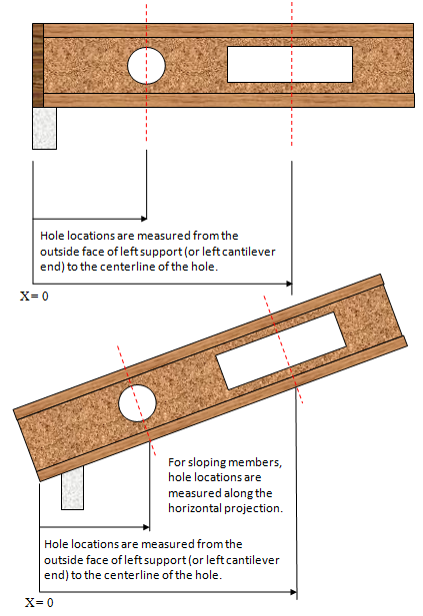
- Enter the location of the hole on the member in the Location field.
- Select vertical offset. If the mid depth check box is selected the hole will always be centered in the vertical direction regardless of product depth. If a vertical offset is entered, this value will apply to all selected product depths. Vertical offset is measured from the top of the member to the vertical centerline of the hole. Not available for vertical holes.
- Enter comments in the Comments field as needed.
To Edit a Hole
- Copy: Click on the copy icon
 in the heading of the hole you want to duplicate. This will add a new hole that is ready for editing.
 - Delete: Click on the delete icon
 in the heading of the hole you want to remove.
Max Hole Size
Only available for horizontal holes at this time.
ForteWEB allows a user to set a location and define a type of hole and the software will calculate the maximum allowed hole at the location, where the hole must maintain a 1/8” clearance to the flange as per TJ-4000 literature (unlike a non-max hole which is still allowed to be full web with no clearance needed). This functionality is limited to only allow one maximum hole in a span. The maximum dimensions for the hole are rounded to the nearest ¼”. When a maximum size hole cannot be found, the following message will be displayed “Software is unable to find a solution for the maximum size hole at ~1”. Additionally, when there are conditions that do not allow for a maximum size hole, the software will not report a hole in the hole grid. The software will effectively analyze the member as if no hole was present, in which you may get a passing design without a hole when a maximum size hole is not allowed.
-
Circular: calculate a circular hole with the largest diameter
-
Rectangular: calculate a rectangular hole that has the largest area (as it is possible to have many solutions that vary in width and height)
-
Rectangular - Max Height: calculate the height of a rectangular hole given the width
-
Rectangular - Max Width: calculate the width of a rectangular hole given the height
-
Slotted: calculate a slotted hole that has the largest area (as it is possible to have many solutions that vary in width and height)
-
Slotted - Max Height: calculate the height of a slotted hole given the width
-
Slotted - Max Width: calculate the width of a slotted hole given the height
Location Shorthand
For easier dimensioning when entering a location, you can use the following shorthands to reference various places along the member:
-
R to reference the right end of the member. Enter R - (minus sign) and a distance to specify a location from the outside face of the right support (or right cantilever end).
-
Support number to reference a support. Enter support number - (minus sign) and a distance to dimension from the left face of that support, or support number + (plus sign) and a distance to dimension from the right face of that support.
-
Support number and | (pipe) to reference the center of a support. For example, "2|" would reference the center of support 2. Or you can offset a distance by adding +/- and the distance depending on the direction.
-
M or C to reference the center of the member. Enter M or C alone or add +/- and the distance to offset from the center of the member. So, entering "C + 2.5" would give you the center of the member plus 2.5".
Check out this Location Shorthand video for more information.
If you enter a distance for the location, it will be measured from the left outside edge of the member.
